knock sensor wiring diagram
The wiring diagram of the mass air flow MAF sensor is different according to the year make and model. The DPFE sensor is often shaped like a small square.
99 02 Ls1 Gm Knock Sensor Wire Harness Gaskets Kits Accessories Engine 98 02 F Body Rpmspeed Com
1999 chevy silverado wiring diagram - silverado wiring harness diagram on 1999 chevy 1500 wiring diagram rh hashtravel co.
. A 3 wire cam sensor receives a hot power source called reference voltage from the ECU. If left unchecked spark knock can cause costly internal engine damage. The manufacturer designs the wiring diagram of the mass air flow sensor according to the need and demand.
The following schematic diagrams contrast the two. Abdualkreem Taha Alfkeer. Nissan navara wiring diagram radio d40 stereo camera nav sat 2006 ae01 alicdn dvd gps rear player bluetooth 2din rav4.
Official City of Calgary local government Twitter account. Car Air Conditioning System. It is the wire through which the oxygen sensor sends the voltage to the computer.
A two-wire oxygen sensor has two wires signal voltage and earth. I only lost. Idle regulation motor and idle switch Hall effect sensor.
A car can have one or two knock sensors depending on its make and model. To learn more about knock sensors and how they can trigger OBD2 codes like P0325 read our technical discussion here. In this powerful guide we will be more general than specific.
Below are the 1 2 and 3. Injection air solenoid valve. For your specific cars ECT sensor wiring diagram you should check your cars owner manual for accurate wire color.
17 Pics about. These eight-pin sensors have two separate ground hot and signal wires. View with cosmetic engine covers removed.
If your LS V-8 powered General Motors Corp. All of these wires are connected to the ECU. First Know The Wiring Diagram Of The Relay.
If youre dealing with an O2 sensor situation and you believe the sensor might need replacing you can watch the sensor on the scan tool data screen with the throttle at about 1200 rpm and you should see about three switches from rich to lean per second with the voltage range being at least from 02 to 08 volts or slightly greater. DPFE Sensor Location. An 8-pin throttle position sensor has a total of eight wires the inside of which are two for motor two are signals two are earth and two are hot wires.
Navara np300 fuse 7zap. Mass Air Flow Sensor Wiring Diagram Mass Air Flow Sensor. The color of the engine coolant temperature sensor varies and is color-coded according to the make and model.
2004 Honda Civic Si 20L. After P0051 is confirmed clears the code and performs a test drive under the same circumstances shown in the freeze frame data. 8 Pin Throttle Position Sensor Wiring Diagram 8 Pin Throttle Position Sensor Wiring Diagram.
The electromagnetic coil circuit consists of two terminals 85 and 86. There have also been several reports of an illuminated air bag warning light in some 2004-2009 2011 and 2013 Mazda 3 redesigns. We carry a wide selection of automotive wiring components parts and accessories like wiring harnesses switches connectors breakers relays and much more.
This page explains very easily. Idle regulation motor and idle switch. 3 Wire Cam Sensor Wiring Diagram 3 Wire Cam Sensor Wiring Diagram.
Nissan navara wiring diagram radio d40 stereo camera nav sat 2006 ae01 alicdn dvd. The knock sensor monitors engine knockthis indicates that the engine is experiencing unusual combustion in the form of detonation or pre-ignition. Wiring Diagram Images Detail.
Absorber closing solenoid valve. 1999 Chevy Silverado Knock Sensor Wiring I Replaced Engine In My. Arduino Due GY-BMP280-33 Pressure Sensor Module I²C Wiring Diagram I²C Wiring to 5V Arduino Uno.
2 Wire O 2 Sensor Wiring Diagram 2 Wire Oxygen Sensor Wiring Diagram. Bosch o2 sensor wiring diagram toyota. Power for the pressure sensor module must be taken from the Arduino 33V pin.
Crankshaft position sensor CKP underside of engine near crankshaft pulley Oil pressure switch backside of engine near oil filter Models Found On. You will see two vacuum hoses attached to the bottom and there is a wiring harness coming from its side. Basically that harness has all 8 injectors and coolant temp sensorThe knock sensor harness is part of the engine control sub-harness 2 which has both knock sensors the MAPBARO solenoid and the EGRC solenoidTop.
The DPFE sensor is often located near the EGR valve. And the second wire is the earth which also goes to the car computer PCM. So a 6-pin accelerator pedal position sensor wiring diagram consists of two ground wires two wiring lines for the input voltage and two signal lines returning to an.
A bidirectional level shifter module can be used to connect the 33V GY-BMP280-33 module I²C pins to a 5V Arduino such as an Arduino Uno or Arduino MEGA. First of all you should know the relay terminals and wiring diagram before understanding the single pole and double pole relay. Fuel tank pressure sensor.
Idle regulation stepper motor MMBA. Code P0325 sets when the PCM determines the knock sensor signal falls outside of a predetermined threshold for a certain amount of time. If you want to know the starter solenoid wiring diagram in simple words.
The wiring diagram for a cruise control system may be included in ACCESSORIES EQUIPMENT section for the specific vehicle manufacturer and the wiring diagram for an anti-lock brake system may be included in BRAKES and WIRING DIAGRAMS for the specific manufacturer. A relay consists of two circuits a coil and high amperage circuit. Of course you should replace the intake manifold gasket and clean all of the parts.
The wiring diagram of the coolant temperature sensor is based on year make and model. Car or truck needs a. The voltage signal wire goes to the car computer.
Where can I find a wiring diagram for the crankshaft sensor to my 2010 Buick enclave. Knock Sensor 3 LED Light Bulb 2 Light Bulb Socket 1 MAP Sensor 1 MAP Sensor Adapter 1. Knock Sensor Location Diagram.
O2 Sensor Wiring Diagram 4 Wire O2 Sensor Diagram - 4 Wire Temperature range is -50 to 302 F. If drive around with the check engine light on when a code P0332 or a P0327 is set in the computer memory engine damage could occur. The 3 wire crank sensor has three wires mentioned below.
Knock sensor KS under intake manifold. 57 - 39 - Knock Sensor 1 59 - 3B - Knock Sensor 2 61 - 3D - Postcatalytic lambda probe heater cylinders 4 5 and 6 62 - 3E - Air mixing system changeover valve. Wiring Diagram 4 Wiring Harness 22 Wiring Harness Connector 5 Wiring Relay.
Keep up with City news services programs events and more. I need to know the colors to the wires and where they run 760. On this powerful page you will learn the starter solenoid wiring especially the 3 pole starter solenoid wiring diagram in understandable language so that you know what wires go to the starter solenoid.
Knock Sensor Wiring Harness. OBD2 Sensors Honda K20A3 Engine Sensor Locations. 33 Nissan 28185 Wiring Diagram.
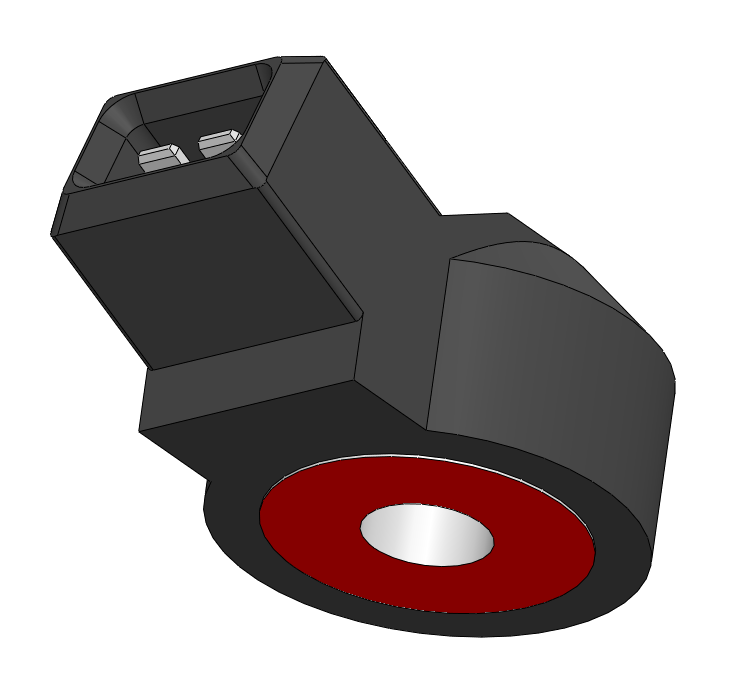
The knock sensor detects abnormal combustion known as spark knock inside of the engine. Common causes of spark knock include low octane fuel overly advanced ignition timing abnormally high engine operating temperatures and carbon buildup inside the engines combustion chambers. This valve is found behind the upper intake manifold which is between the motor and the firewall.
While this issue is mainly caused by damaged wiring in the seatbelt pretensioner sensor some owners have also reported that a blown bulb in the dashboard and a misaligned spring from the sensor caused the issue.
Knock Sensors
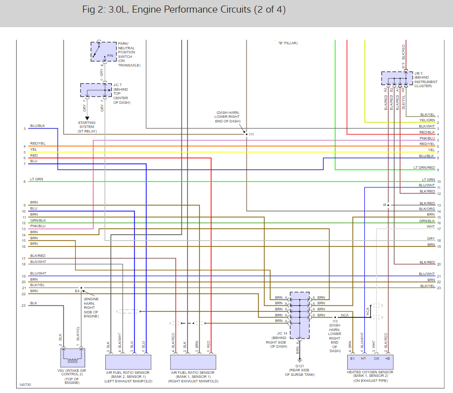
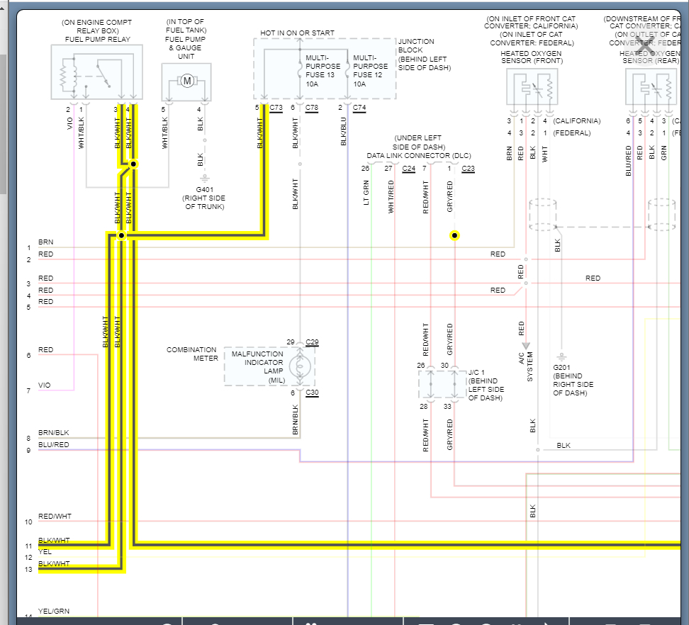
Engine Wiring Diagrams Please Getting P0330 Code For Bank 2
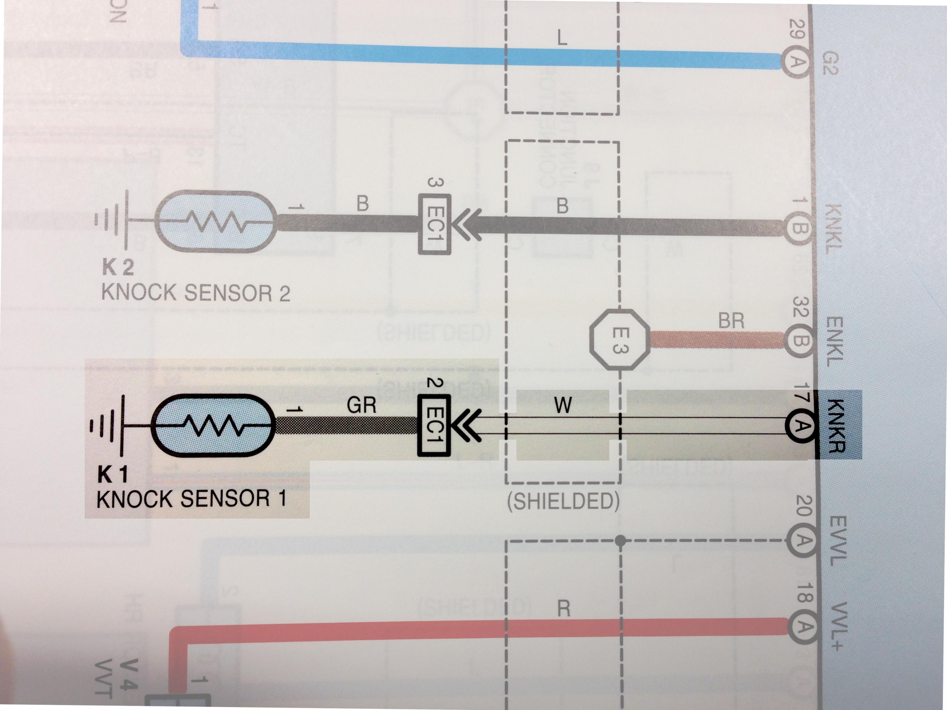
Ecu Pin Diagram For A 2001 Lexus Gs430 Clublexus Lexus Forum Discussion

P0327 52 P0328 52

Dtc P0325 Knock Sensor 1 Circuit Malfunction Bank 1 Dtc
1992 K3500 Trying To Locate Knock Sensor Wire Gm Truck Club Forum
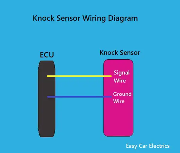
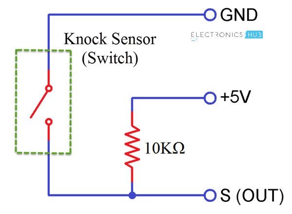
1 2 3 Wire Knock Sensor Wiring Diagram With Picture Easy Car Electrics

Amazon Com Genuine Toyota Lexus Knock Sensor Harness 82219 07010 Automotive

Knock Sensor Toyota Nation Forum
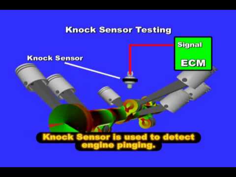
Knock Sensor Operation Youtube

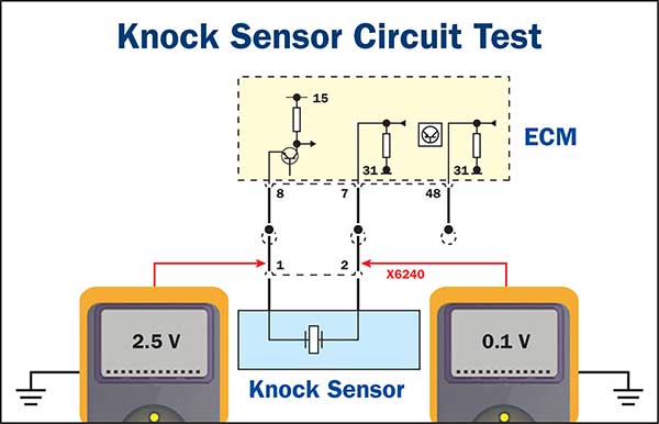
How To Test Knock Sensor Youtube
Knock Sensor Wiring Diagram Did Not Sensor Wire Pigtail Connector
Hyundai Elantra Knock Sensor Ks Schematic Diagrams Engine Control System Fuel System Hyundai Elantra Md 2010 2015 Service Manual
Kia Niro Knock Sensor Ks Schematic Diagrams Engine Control System
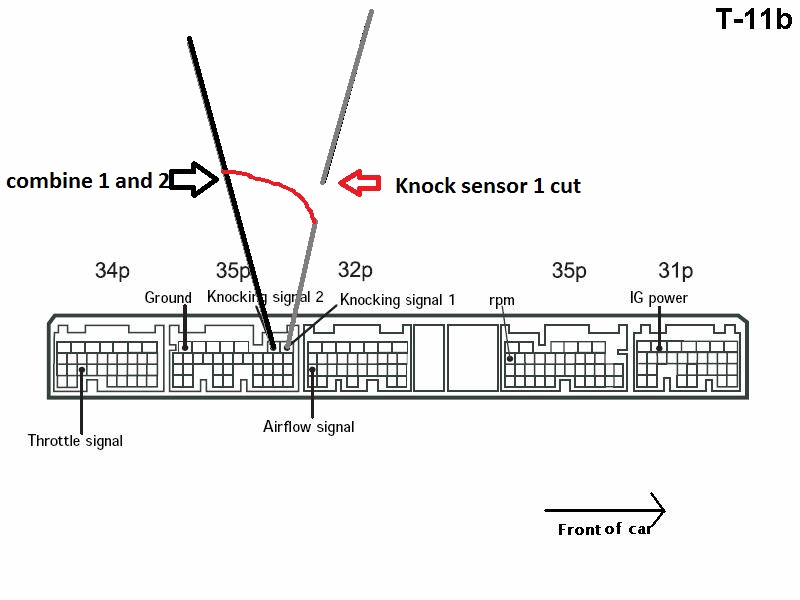
Looking For Ecm Pinout Ls430 For Knock Sensor Hack Page 3 Clublexus Lexus Forum Discussion
Knock Monitor Instructions Manual V2 0
1999 Chevy Silverado Knock Sensor Wiring I Replaced Engine In My